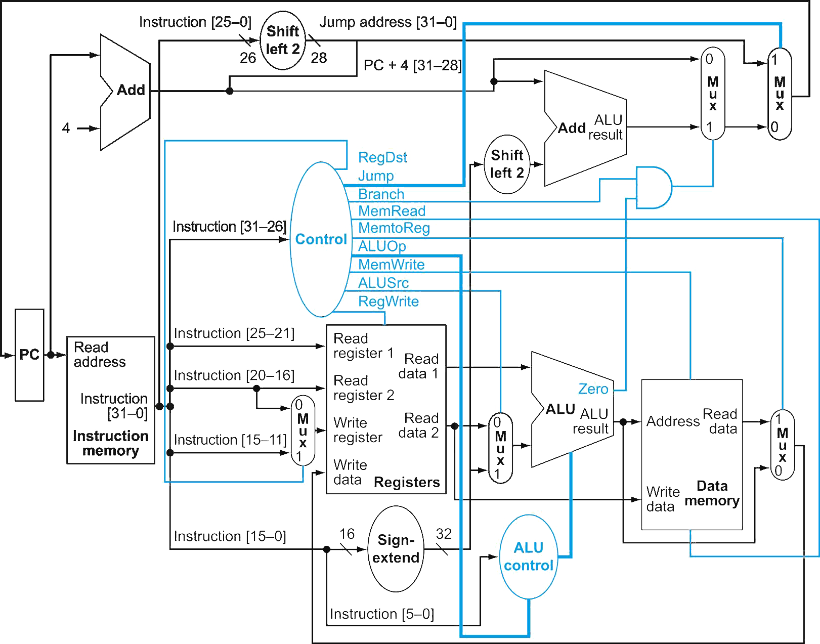
this page covers chapter 4. but some of terms and concepts was already covered in Logic Circuits
-
A single cycle processor is a processor that carries out one instruction in a single clock cycle. (that is )
-
These are the instructions we will implement:
- R-type instructions:
add,sub,and,or,slt - I-type instructions:
lw,sw,beq - J-type instructions:
j
- R-type instructions:

- Fetch
- Decode
- Execute
- Memory
- Write Back
Logic Design Conventions
-
Datapath elements are classified into two types:
- Combinational elements (e.g. ALU, AND gate)
- State elements (e.g. Registers, Memory (data, instruction))
-
clock methodology: edge-triggered (positive, rising edge)
-
nearly all elements are 32-bit wide
-
buses are indicated with thicker lines
Control
Main Control Unit
- Input: 6-bit opcode (
instruction[31-26]) - Output:
- RegDst: Whether write to register
rt(0) orrd(1) - RegWrite: Whether Write register register is written with Write data value
- ALUSrc:
- 1 = the 2nd ALU operand is the sign-extended 16-bit immediate value,
- 0 = the 2nd ALU operand comes from the 2nd register file output (Read data 2)
- MemRead: 1 = read from memory
- MemWrite: 1 = write to memory
- MemtoReg:
- 0 = the ALU result is written to the register file
- 1 = the memory data is written to the register file
- Branch: 1 = branch
- ALUOp: 2-bit control signal for ALU operation
- Jump: 1 = jump, 0 = don’t jump
- RegDst: Whether write to register
| Instr. | Opcode | RegDst | ALUOp1 | ALUOp0 | ALUSrc | Branch | MemRead | MemWrite | RegWrite | MemtoReg | Jump |
|---|---|---|---|---|---|---|---|---|---|---|---|
| R | 000000 (0) | 1 | 1 | 0 | 0 | 0 | 0 | 0 | 1 | 0 | 0 |
lw | 100011 (35) | 0 | 0 | 0 | 1 | 0 | 1 | 0 | 1 | 1 | 0 |
sw | 101011 (43) | X | 0 | 0 | 1 | 0 | 0 | 1 | 0 | X | 0 |
beq | 000100 (4) | X | 0 | 1 | 0 | 1 | 0 | 0 | 0 | X | 0 |
addi | 001000 (8) | 0 | 0 | 0 | 1 | 0 | 0 | 0 | 1 | 0 | 0 |
j | 000010 (2) | X | X | X | X | X | 0 | 0 | 0 | X | 1 |
jm | 0x3f=111111 | X | 0 | 0 | 1 | 1 | 1 | 0 | 0 | X | 1 |
ALU Control Unit
Determine the 4-bit ALU control signal based on ALUOp signals and funct code.
- Input:
- : 1-bit control signal (from the control unit)
- : 1-bit control signal (from the control unit)
- : 6-bit function code (from
instruction[5-0])
- Output:
- 4-bit control signal for ALU operation (will be used to determine as the ALU operation in the ALU)
- 4-bit control signal for ALU operation (will be used to determine as the ALU operation in the ALU)
| Input 1 | Input 2 | Output | |||
|---|---|---|---|---|---|
| opcode | Funct () | Instruction Operation | Operation | ||
| 00 | LW, SW | XXXXXX | load,store | 0010 | add |
| 01 | beq | XXXXXX | branch equal | 0110 | sub |
| 10 | R | 100000 | add | 0010 | add |
| 10 | R | 100010 | subtract | 0110 | sub |
| 10 | R | 100100 | AND | 0000 | and |
| 10 | R | 100101 | OR | 0001 | or |
| 10 | R | 101010 | slt | 0111 | slt |